Adaptive Trees on a GPU: Efficient GPU-aware Adaptive Tree Construction for the Fast Multipole Method
Abstract. The Fast Multipole Method (FMM) reduces the cost of long-range particle interactions from
Keywords: fast multipole method, adaptive octree, space-filling curves, GPU, CUDA Graphs, k-d tree
Interactive figures
Most figures are interactive. Use ◀ ▶ to step through algorithms, drag the sliders, hover arrays and click plots to enlarge them. The algorithm figures run small JavaScript models of the kernels, so numbers shown in them belong to toy examples. All measurements come from the benchmark suite described in Section 7.
1. Introduction
Particle simulations in molecular dynamics, plasma physics and astrophysics are dominated by long-range interactions between all pairs of particles. Evaluating these pairs directly costs
The structure of this hierarchy determines the balance between near-field and far-field work. Large leaves cause many expensive direct interactions, while small leaves cause many boxes and expansion translations. For non-uniform distributions, such as an expanding Coulomb explosion or a thin disk in an otherwise empty domain, a uniform tree is either too coarse where the particles are or wastes most of its boxes on empty space. An adaptive tree refines only where it is needed.
On a GPU, adaptivity comes at a price. Pointer-based trees are irregular, require dynamic allocation and are difficult to build in parallel. In a time-stepping simulation the tree additionally has to follow the particles every step, so construction is a recurring cost. If updating the tree takes as long as the FMM saves, nothing is gained.
This project builds on the Cornerstone library [2], which represents an adaptive octree as a sorted array of space-filling-curve keys and updates it with bulk-parallel primitives. The FMM code used at JSC, FMSolvr [3], however needs an explicit hierarchy with a specific node layout, per-node particle ranges and a particle-to-leaf mapping, and ideally a tree that is refined according to the work the FMM will actually perform. This report makes the following contributions:
- NFCount, a refinement criterion based on the estimated near-field work of a leaf and its 27-cell neighbourhood (Section 3.3).
- A direct TreeView construction that derives all internal nodes and their final positions in FMSolvr's layout from the boundary array, without tree traversal (Section 4).
- A series of GPU optimisations that make repeated updates cheap, culminating in a CUDA-Graph-compatible update (Section 5).
- A binary adaptive tree that reuses the same representation and view construction (Section 6).
Section 2 introduces the FMM, adaptive trees and the Cornerstone representation. Sections 3 to 6 present the methods, Section 7 the experimental setup and Section 8 the results. Section 9 outlines future work and Section 10 concludes.
2. Background
2.1 The Fast Multipole Method
The FMM [1] [4] organises the particles in a hierarchy of nested boxes. The interaction between two groups of particles that are well separated, i.e. far apart compared to their size, is approximated by truncated multipole and local expansions. Figure 1 shows the resulting operators.
| P2M · M2M | upward: particles → multipoles → parents |
| M2L | far field between well-separated nodes |
| L2L · L2P | downward: parents → children → particles |
| P2P | direct near field between neighbouring leaves |
The cost splits into two parts with opposite dependence on the tree. The far field scales with the number of boxes and the expansion order. The near field scales with the number of particle pairs in neighbouring leaves and grows quadratically with the leaf occupancy. Refining a leaf therefore trades near-field work for far-field work, and a good tree balances the two locally. Since multipoles are passed up and local expansions down through all internal nodes, the FMM also needs the full hierarchy, not only the leaves.
2.2 Dense, Sparse and Adaptive Trees
Figure 2 compares three ways to build the resulting tree. A dense tree subdivides the whole volume to the same depth. Its layout is perfectly regular and GPU-friendly, but empty boxes are stored and processed and the depth cannot follow the local density. A sparse tree stores only occupied boxes, typically linked by pointers. It is memory-efficient, but pointer chasing, scattered accesses and dynamic allocation map poorly to GPUs. An adaptive tree refines dense regions and keeps coarse cells elsewhere. As the following sections show, it can be stored in contiguous arrays and updated with regular parallel primitives.
Dense
341 nodes256 leaves220 emptydepth 4
Sparse
59 nodes36 leaves0 emptydepth 4
Adaptive
113 nodes85 leaves17 emptydepth 6
2.3 Space-Filling Curves and the Cornerstone Representation
A pointer-free tree requires an address for every cell. Each particle position is quantised onto an integer grid and the coordinate bits are interleaved into a Morton key. In the 3D octree, every three bits select one of eight children on the next level, so a cell at level
x = 5101
y = 2010
interleave ↓ (x bit, y bit) per level
key100110= 38
digitsL1: 2L2: 1L3: 2
Each 2-bit digit selects a quadrant one level deeper (dashed squares). A cell at level ℓ therefore owns the contiguous key interval that shares its first ℓ digits. This is what makes a tree representable by sorted keys alone.
After key generation, the particles are radix-sorted as key/permutation pairs. P holds the sorted keys and Perm[p] the original slot of the particle at sorted position p. Note that numerical proximity of keys does not imply geometric proximity, since neighbouring cells across a high-level boundary can have very different keys. Neighbour queries therefore have to be formulated geometrically (Section 3.3).
Cornerstone [2] stores an adaptive tree only by the boundaries of its leaves, which partition the key space into consecutive intervals:
A short interval corresponds to a deep, small leaf and a long interval to a coarse leaf. The array contains neither internal nodes nor pointers. Together with the particle counts P, it forms the complete state that is kept between time steps. Every split replaces a leaf by all eight children, including empty ones, so the represented tree is a full octree. This property is essential for the node-count formulas in Section 4. Figure 4 shows how
K =064
root · 1 leaves → K has 2 entries · hover a leaf
3. Adaptive Tree Update
3.1 Parallel Rebalancing
An update decides for every leaf independently whether it should split, stay or merge with its seven siblings. Each decision is encoded as the number of output leaves (8, 1 or 0). An exclusive prefix sum over these numbers yields the output position of every leaf, after which all threads write their new boundaries independently. A rebalance pass thus consists of three bulk-parallel steps: decide, scan and scatter. Figure 5 illustrates one pass on a toy octree with 22 leaves that is reused throughout this report.
· 22 leaves, 29 particles · key space [0, 512)
Leaf i owns the key interval [K[i], K[i+1]). Shade = depth. Red counts exceed the threshold. Hover a leaf to highlight its particles.
A merge is encoded implicitly. The first sibling contributes one boundary and the other seven contribute none, so the remaining boundary extends over the whole parent. An operation of 1 therefore either keeps a leaf or marks the leader of a merge, a distinction that becomes important for caching in Section 5.2. Heavily overfull leaves are split by several levels at once (64, 512 or 4096 children), which saves complete decide, scan and scatter rounds:
cpp
...
    if (count > bucketSize * 512 && level + 3 < maxTreeLevel<KeyType>{})
        return 4096;
    if (count > bucketSize * 64 && level + 2 < maxTreeLevel<KeyType>{})
        return 512;
    if (count > bucketSize * 8 && level + 1 < maxTreeLevel<KeyType>{})
        return 64;
    if (count > bucketSize && level < maxTreeLevel<KeyType>{})
        return 8;
...
Source: src/octree/octree_rebalance.cuh, commit d830fc3, lines 215–225.
For NFCount the jump thresholds grow by a factor of 64 instead of 8 per level, since the occupancy drops by about 8 per level and the quadratic interaction work by about 64.
3.2 Incremental Updates
Because
3.3 FMM-aware Refinement: NFCount
Cornerstone’s criterion, LeafCount, splits a leaf when it contains more than a fixed number of particles. For the FMM, this criterion is extended to account for the surrounding particle distribution. The cost caused by a leaf is dominated by its near field, i.e. the direct interactions of its particles with all particles in neighbouring boxes. A leaf with few particles next to a dense cluster can therefore be far more expensive than its own particle count suggests. NFCount estimates this work as
where
For a uniformly populated neighbourhood, where each stencil cell contains approximately
which corresponds to the near-field work of a uniformly populated neighbourhood with the LeafCount default of 64 particles per cell. Figure 7 compares both criteria on the same leaf.
3D: leaf + 26 same-level neighbours
LeafCount · particles in the leaf
Ni = 7
NFCount · leaf + 3×3 same-level stencil
NFi = 7 · (7 + 268) = 1925
same leaf in both panels · hover another leaf · 2D toy: 3×3 stencil (3D: 3×3×3)
Counting geometry instead of leaves. The first implementation 1755802 searched neighbours in the leaf array and only accepted a leaf of exactly the same level. Wherever the neighbourhood was represented by coarser or finer leaves, its particles were missed, and only a directional subset of the stencil was evaluated. The final version e7bd16a instead queries the particles. Each stencil cell is a key interval
which is correct regardless of how the tree is refined around the leaf.
Merging. Eight siblings may only merge if their hypothetical parent stays below the threshold. Since the parent has a larger stencil, its work cannot be derived from the children's values and is evaluated explicitly, once per sibling group 6f11cac.
A naive evaluation of NFCount requires 54 binary searches per leaf, with two searches for each of the 27 stencil cells. In comparison, LeafCount requires only two binary searches per leaf. Reducing this overhead is the subject of Section 5.
4. TreeView Construction
computeSfcKeys · sort · updateOctreeGpu · buildOctreeGpu
adaptive update · TreeView
inner ring: tree-update phaseview phasenot computed
4.1 Child-Centric Layout
FMSolvr stores the nodes level by level and expects the children of a level in child-centric order: first child 0 of every parent, then child 1 of every parent, and so on 3c99271. With
where
A = node 6B = node 7C = node 8
A09
B010
C011
A112
B113
C114
A215
B216
C217
A318
B319
C320
A421
B422
C423
A524
B525
C526
A627
B628
C629
A730
B731
C732
hover a child slot
childIndex[p] always points to child 0. With level offsets known, M = (levelOffset[ℓ+2] − levelOffset[ℓ+1]) / 8, so no per-node child list is needed.
4.2 From Breadth-First Search to Direct Reconstruction
The child-centric layout introduces a dependency between consecutive levels. To place the children of a level, the number of internal parents
The view construction went through four versions. The first c4719cd copied
The fourth version 8041613 eliminates the traversal altogether. Instead of discovering the hierarchy and its per-level sizes level by level, it derives them directly from the leaf boundaries in
All sizes are known in advance. Every internal node has eight children and every node except the root has exactly one parent. Counting edges gives for
and in general
Every internal node corresponds to exactly one boundary in
cpp
const KeyType leftStart = K[i];
const KeyType rightStart = K[i + 1];
const unsigned level = lcaLevel<LevelBits>(leftStart, rightStart);
const KeyType parentStart =
    nodeStartAtLevel<LevelBits>(rightStart, level);
const unsigned rightChild =
    childSlotAtLevel<LevelBits>(rightStart, parentStart, level + 1);
// For either full tree, rightChild == 1 means this
// boundary is exactly:
//
//     child0 subtree | child1 subtree
const bool canonical = (rightChild == 1);
Source: src/common/tree_view.cu, commit d830fc3, lines 185–199 (abridged).
In the toy octree of Figure 5, boundary 64 identifies the root and boundaries 8 and 136 identify root children 0 and 2. The leaf histogram per level
The remaining stages compact the flagged candidates, sort them, and write every node directly to its final position
where
Input: Cornerstone K
0481216323640444864
L = 10 leaves. Every internal node has 2b = 4 children ⇒
#internal = (L − 1) / (2b − 1) = 3
sizes are known analytically, before building anything.
4.3 One Sort Instead of Two
The child-centric order requires internal nodes sorted by level and, within a level, by their child path read backwards. The first direct implementation used two radix sorts. Commit 8e958d5 combines both criteria into a single key,
Since the reversed path of a level-
| # | node path | level | reversed path |
|---|---|---|---|
| 0 | root | 0 | — (0) |
| 1 | 0 | 1 | 0 (0) |
| 2 | 0·3 | 2 | 3·0 (24) |
| 3 | 0·7 | 2 | 7·0 (56) |
| 4 | 2 | 1 | 2 (2) |
| 5 | 2·1 | 2 | 1·2 (10) |
| 6 | 2·6 | 2 | 6·2 (50) |
Internal nodes in level-grouped SFC order (what the classify/compact stages produce). Paths are octal child digits from the root.
Particle ranges. The particle range of a leaf requires no search, since the leaf counts are already known. An exclusive scan over
5. GPU Optimisations
The previous sections define what is computed. Most of the project time went into how it is computed on the GPU. Figure 13 shows the 34 commits of the repository. They fall into four phases: making the tree usable for the FMM (late August), making NFCount correct and parallel (early September), avoiding repeated work (mid September) and removing the CPU from the update path (second half of September), followed by the binary tree.
Hover or click a commit. ★ = milestones that changed the performance picture.
5.1 Cooperative Stencil Evaluation
Instead of one thread evaluating all 27 cells, a cooperative group of eight threads shares one leaf e7bd16a. Lane
numbers = particles in each same-level geometric cell · #13 = the leaf itself
| lane | cells | partial sum |
|---|---|---|
| 0 | 0, 8, 16, 24 | 0 |
| 1 | 1, 9, 17, 25 | 0 |
| 2 | 2, 10, 18, 26 | 0 |
| 3 | 3, 11, 19 | 0 |
| 4 | 4, 12, 20 | 0 |
| 5 | 5, 13, 21 | 0 |
| 6 | 6, 14, 22 | 0 |
| 7 | 7, 15, 23 | 0 |
8 threads cooperate on one leaf. Cell c goes to lane c mod 8.
cpp
// 27 = 3x3x3 same-level neighborhood, including the node itself
for (int cell = tile.thread_rank(); cell < 27; cell += tile.size())
{
    int dx = cell % 3 - 1;
    int dy = (cell / 3) % 3 - 1;
    int dz = cell / 9 - 1;

    KeyType cellKey =
        (cell == 13) ? nodeStart
                     : sfcNeighbor<KeyType>(ibox, level, dx, dy, dz, isHilbert);

    std::size_t first = std::size_t(
        lowerBound(particleKeys, particleKeys + numParticles, cellKey) -
        particleKeys);
    std::size_t last = std::size_t(
        lowerBound(particleKeys, particleKeys + numParticles, cellKey + range) -
        particleKeys);

    unsigned long long population =
        static_cast<unsigned long long>(last - first);
    populationSum += population;
    if (cell == 13)
        centerCount = population;
}

populationSum += tile.shfl_down(populationSum, 4);
populationSum += tile.shfl_down(populationSum, 2);
populationSum += tile.shfl_down(populationSum, 1);
Source: src/octree/octree_rebalance.cuh, commit d830fc3, lines 579–634 (abridged).
This distributes the searches but does not reduce their number. The following optimisation does.
5.2 Caching and Compaction
Within one update pass over DeviceSelect then compacts the dirty flags into a dense index list, so the cooperative kernels only process leaves that require work 6d19359. For
leaf0123456781624324048566472808896104112120128192256320384448
reuse N, NF········✓✓✓✓✓✓✓·········✓✓✓✓✓
nfDirty11111111000000011111111100000
selected01234567151617181920212223
NF queries without caching
54 × 29 = 1566
with dirty flags + compaction
54 × 17 = 918
saved binary searches
648
■ split children · ■ merge leader (new, larger cell that must be recomputed although its op is 1) · ■ identical interval → N and NF copied from the old arrays.
Launch configuration. Later commits adapted the launch configuration to each workload 8e958d5 1d220c6. LeafCount refreshes use one thread per leaf instead of an eight-thread group with a single busy lane, full refreshes skip the selection of the identity list, and the evaluation of the leaves and of the hypothetical parents runs on separate streams.
5.3 Memory Management
Every rebalance pass and time step changes the number of leaves and with it the size of many buffers, including resize() causes two costs. If the capacity is exceeded, new memory is allocated and the data copied. If the vector grows within its capacity, every newly exposed element is value-initialised by a fill kernel, although the next kernel overwrites it anyway. The second cost does not disappear by reserving enough memory. Profiling a single snapshot showed 23 initialisation kernels while not a single allocation was required.
time step 1 · required size 1000
ordinary resize()alloc
exact capacity · value-initialises new elements
alloc 1init 1000host resize 1
resizeWithHeadroomalloc
+25 % capacity · resize(n, thrust::no_init)
alloc 1init 0host resize 1
prepared graph capacityalloc + capture
fixed storage · logical count lives on the device
alloc 1init 0host resize 1recapture 1
capacitylogical size (written by the kernel)newly exposed → value-initialised, then overwrittenallocation this step
Commit 65b11a5 therefore replaces all resizing in the tree, rebalance and view code by a helper that grows the capacity by 25% only when necessary, never shrinks it, and changes the logical size without initialisation:
cpp
template <class T>
void resizeWithHeadroom(thrust::device_vector<T> &buffer,
                        std::size_t required)
{
    if (required > buffer.capacity())
    {
        const auto extra = required / 4;
        const auto limit = buffer.max_size();

        // Add 25% without overflowing; reserve handles oversized requests.
        const auto capacity =
            required <= limit && extra <= limit - required
                ? required + extra
                : required;

        buffer.reserve(capacity);
    }

    buffer.resize(required, thrust::no_init);
}
Source: src/helpers.cuh, commit 65b11a5, lines 6–25.
Buffers whose initial contents matter, such as histograms and flags, are still cleared explicitly. Two smaller changes reduce memory traffic further. Key generation writes the identity permutation directly instead of launching a separate kernel, and the permutation uses 32-bit instead of 64-bit indices 1914b3d, which reduces the sort payload from 16 to 12 bytes per particle.
5.4 Overlapping Independent Work
Many stages depend on the same inputs but not on each other. In the view construction, for example, the scan over
makespan 13.5 vs serial 19.0 units
Hover a task to see the events it waits on. Durations are illustrative units, not measurements. Overlap creates an opportunity, it does not guarantee perfect concurrency on a busy GPU.
5.5 CUDA Graphs
After these optimisations, a significant part of each update was no longer GPU work but coordination between CPU and GPU. After every pass the host read the new leaf count, decided whether the tree had changed, resized buffers, swapped pointers and launched the next kernels, leaving the GPU idle during each round trip. CUDA Graphs avoid this overhead by capturing a sequence of launches once and replaying it with a single call, provided that addresses and structure remain fixed. Commits f19e711 and 93b637d rebuild the update around this constraint. The leaf count, the convergence flag and the active input buffer are stored in a state struct on the device, and kernels select their input and output arrays themselves. A fixed number of passes is recorded, and kernels scheduled after convergence return immediately. All buffers are prepared for a fixed capacity, and a proposal that would exceed it is rejected before anything is written:
cpp
__global__ void graphCheckCapacityKernel(const std::int64_t *nodeOps,
                                         TreeNodeIndex leafCapacity,
                                         RebalanceState *state)
{
    if (state->converged)
        return;
    if (state->needsResize || !state->changed)
    {
        state->converged = 1;
        return;
    }
    const std::int64_t proposedLeaves = nodeOps[leafCapacity];
    if (proposedLeaves > leafCapacity)
    {
        // Reject the complete proposal: the old tree and its freshly
        // computed counts remain valid, with no partially applied splits.
        state->needsResize = 1;
        state->converged = 1;
        return;
    }
    state->newNumLeaves = TreeNodeIndex(proposedLeaves);
}
Source: src/octree/octree_rebalance.cuh, commit d830fc3, lines 1211–1232.
The old tree then remains valid, and growth and recapture happen outside the replay (Figure 19). Two costs remain: a status readback after each replay, and capacity-sized work such as the CUB scan that runs regardless of convergence. Moreover, the default of two passes per octree update does not always reach full convergence on rapidly changing data.
One launch replays a fixed number of passes. RebalanceState on the device holds the leaf count, convergence flag and active A/B buffer. Kernels after convergence exit immediately (grey slivers), but the capacity-sized CUB scan still runs. An oversized proposal is rejected before anything is written; growth and recapture happen outside the replay.
Escaped particles. Particles that leave the domain would change the particle count and thus the buffer sizes inside the graph. Since 056d000 they keep their slot but receive the maximum key, so the sort moves them to the end of P and the device determines the active prefix (Figure 20).
input slot
key3756118449MAX271333
sorted P5913182733374461MAX
Perm1583790426
Click a slot to let that particle escape the domain. Active particles: 9 / 10 slots. The tree counts and views only see the active prefix, and escaped entries map to an invalid node index. Note that key generation and the sort still touch all slots.
6. Binary Adaptive Trees
An octree split always halves all three axes. A region that only requires refinement in one direction, such as a thin sheet or a filament, still receives eight children. A binary tree splits one axis at a time. Three binary levels reproduce one octree level, but an adaptive binary tree can stop earlier or refine only selected branches (Figure 21).
The binary tree always splits the longest side at its midpoint [5]. Since all cells at a given depth then have the same shape, a single axis schedule describes the whole tree and also supports rectangular domains 806464e:
cpp
for (unsigned depth = 0; depth < maxBinaryDepth; ++depth)
{
    unsigned axis = 0;
    if (length[1] > length[axis]) axis = 1;
    if (length[2] > length[axis]) axis = 2;
    geometry.axis[depth] = std::uint8_t(axis);
    length[axis] *= 0.5L;
}
Source: src/kdtree3d/binary_node.cuh, commit d830fc3, lines 31–38.
The key encoding interleaves the coordinate bits in the same order, so every cell is again a contiguous key interval (Figure 22). The result is a linear kd-tree [6] on which the Cornerstone machinery carries over unchanged, including rebalancing, device state and capacity handling. The direct view construction only relies on every internal node having a unique boundary between its first two subtrees, which holds for any full tree. It was therefore generalised to
K =064
root · 1 leaves → K has 2 entries · hover a leaf
For the same number of leaves, a binary tree has more internal nodes (
Quadtree (octree in 3D)
| leaves | 106 | empty | 32 (30 %) |
| nodes | 141 | avg / leaf | 4.0 |
| depth 6 | |||
Binary tree (KDTree3D)
| leaves | 77 | empty | 21 (27 %) |
| nodes | 153 | avg / leaf | 5.5 |
| depth 11 ≈ 5.5 quad levels | |||
7. Experimental Setup
All construction benchmarks were run on an NVIDIA GeForce RTX 5060, compiled with nvcc 13.3 and g++ 14.2 using -O3 for sm_120, and with 64-bit Morton keys for every version. To show the evolution of the project, intermediate states of the repository were rebuilt from their commits (Table 1). The full-pipeline measurements in Section 8.4 were obtained with a separate FMM harness on an NVIDIA RTX 5060 Ti.
| Label | Source | Execution |
|---|---|---|
| Cornerstone (baseline) | Cornerstone d7fddfb4 | direct |
| early September | e7bd16a with fork efd7e418 | direct |
| mid September | ea89b79 | direct |
| final | d830fc3 | CUDA Graph |
Table 1. Measured versions. All versions receive the same bounding box, particle order and key type.
Three configurations are evaluated: octree with LeafCount (64 particles per leaf), octree with NFCount (
| Dataset | Particles | Type | Character |
|---|---|---|---|
| Coulomb explosion | 114 537 | 7 088 snapshots | starts dense, expands |
| Flyby | 512 002 | 1 201 snapshots | thin disk in a mostly empty domain |
| Cluster simulation | 10 000 | 53 snapshots | small, clustered |
| NaCl | 6 740 | single + noise | small, crystalline |
| STMV | 1 066 628 | single + noise | biomolecular, dense |
| Dense halo | 25 600 000 | single + noise | large, dense |
Table 2. Datasets. Single snapshots are replayed with cumulative Gaussian noise (σ = 10⁻³ of the bounding-box edge) to emulate time steps.
The measurement methodology follows Hoefler and Belli [7]. Warm-up runs are excluded, every configuration is repeated in at least ten independent processes, and per-step medians with bootstrapped 95% confidence intervals are reported. The tree-update phase covers key generation, sorting and rebalancing, and the view phase covers the TreeView construction. For Cornerstone, the view phase is its linked-octree construction, which produces fewer arrays. A correctness gate compares the outputs of all versions before any measurement.
8. Results
8.1 Construction Compared with Cornerstone
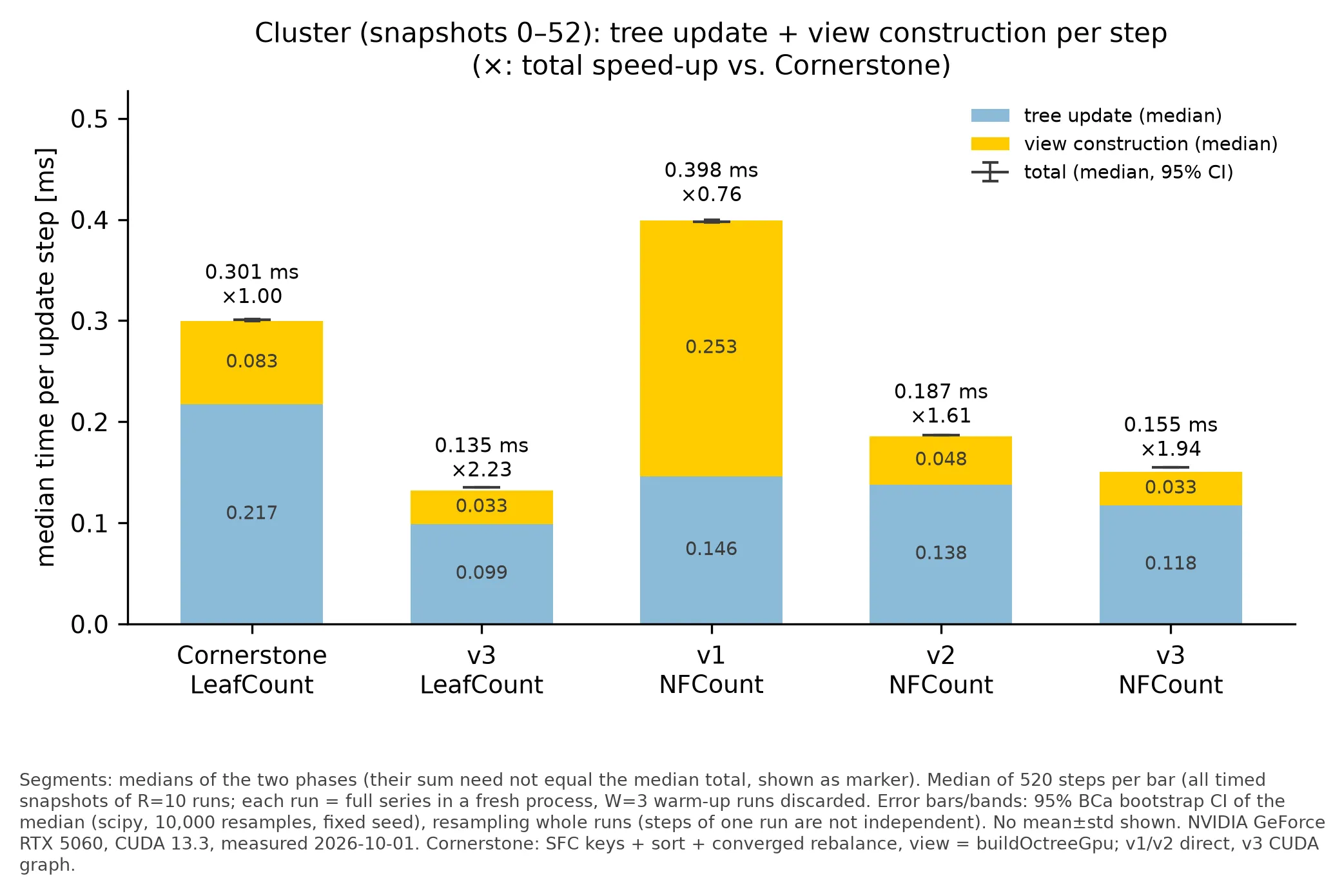
Table 3 and Figure 24 compare the final version with Cornerstone. On the small and medium time series, the LeafCount tree is built 2.0–2.4× faster while producing considerably more output. Even with NFCount, which requires 54 instead of two binary searches per fresh leaf evaluation, the construction remains 1.35–1.94× faster. On the cluster dataset, the resulting leaf arrays match Cornerstone's exactly for all 53 snapshots. The advantage shrinks for the large single-snapshot datasets. On STMV, LeafCount is still 1.16× faster, and on the 25.6-million-particle dense halo it is on par with Cornerstone, while NFCount is slower since the stencil searches dominate.
| Dataset | Cornerstone | final, LeafCount | final, NFCount |
|---|---|---|---|
| Cluster simulation | 0.301 ms | 0.135 ms (2.23×) | 0.155 ms (1.94×) |
| Coulomb explosion | 0.405 ms | 0.170 ms (2.38×) | 0.221 ms (1.83×) |
| NaCl | 0.266 ms | 0.131 ms (2.04×) | 0.142 ms (1.87×) |
| Flyby | 0.978 ms | 0.466 ms (2.10×) | 0.725 ms (1.35×) |
| STMV | 0.866 ms | 0.745 ms (1.16×) | 1.004 ms (0.86×) |
| Dense halo | 27.87 ms | 27.92 ms (1.00×) | 40.67 ms (0.69×) |
Table 3. Median time per step (tree update and view construction) and speedup over Cornerstone.
Note that Cornerstone converges every update completely, whereas the final version performs two passes. On the Flyby, the two trees therefore agree at only 9 of 1 201 snapshots, and the speedup compares different convergence policies.
tree updateview constructionmedian total
Cornerstone
baseline · LeafCount
not measured
early September
NFCount · GPU-BFS views
not measured
mid September
NFCount · direct views, caching
not measured
final
NFCount · CUDA Graph
not measured
final
LeafCount · CUDA Graph
not measured
Medians per time step. Phase and total medians are computed separately, so the bars need not add up exactly to the tick. Speed-up relative to Cornerstone. Hover a row for details.
8.2 Evolution over the Project
The intermediate versions show where the speedup originates. On the cluster dataset with NFCount, the early-September version, which already produced the full FMM output on the GPU, required 0.398 ms per step (0.76× compared with Cornerstone), mostly due to the breadth-first view construction (0.253 ms). Direct reconstruction and caching reduced the total to 0.187 ms by mid September (2.1×), with the view construction alone becoming 5.3× faster. CUDA Graph execution, launch tuning and the remaining optimisations then gave another 1.2× to 0.155 ms. The Flyby follows the same pattern, from 1.93 ms over 1.14 ms to 0.72 ms. Since each version bundles several commits, the measurements do not attribute speedups to individual optimisations.
8.3 Behaviour over Time
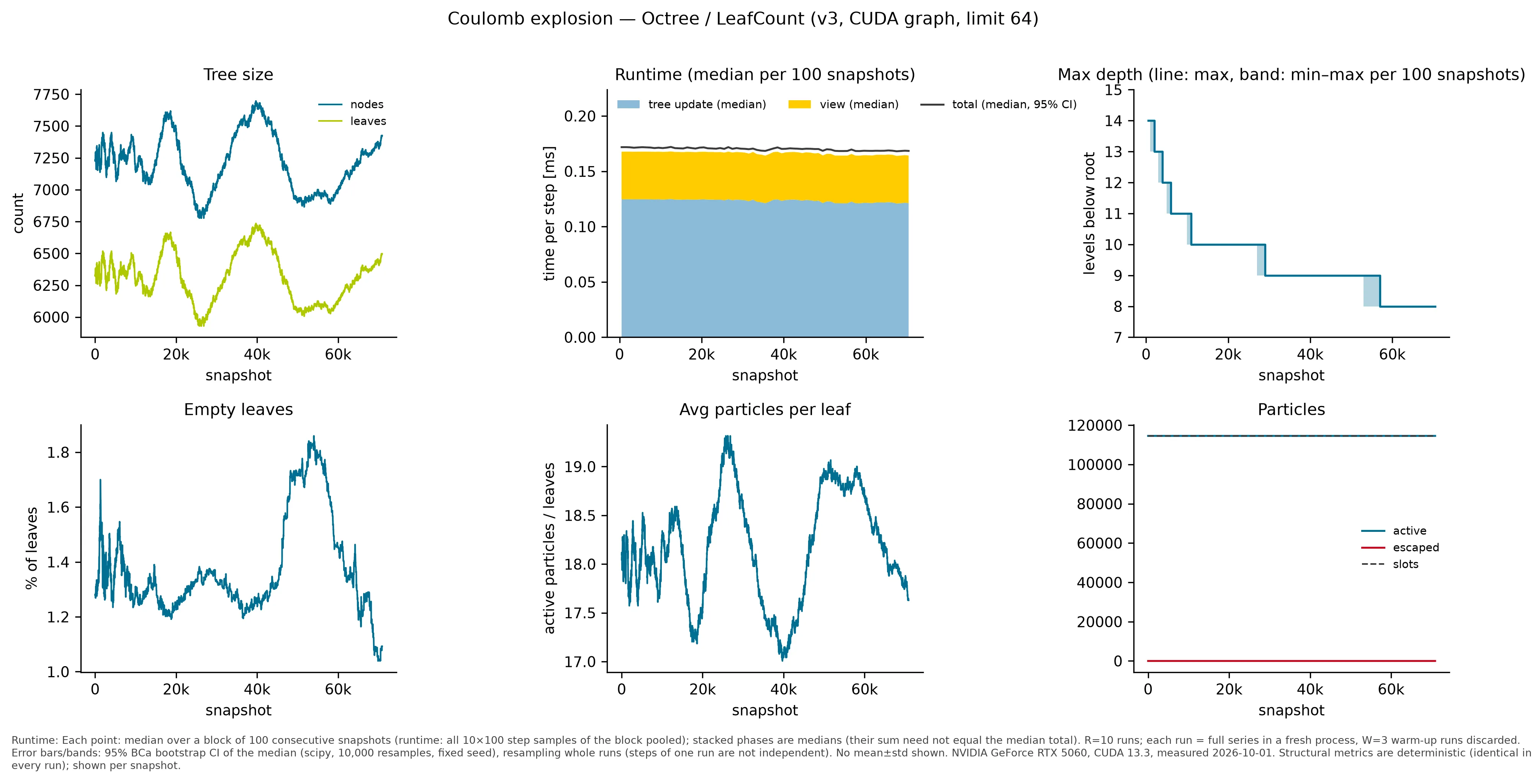
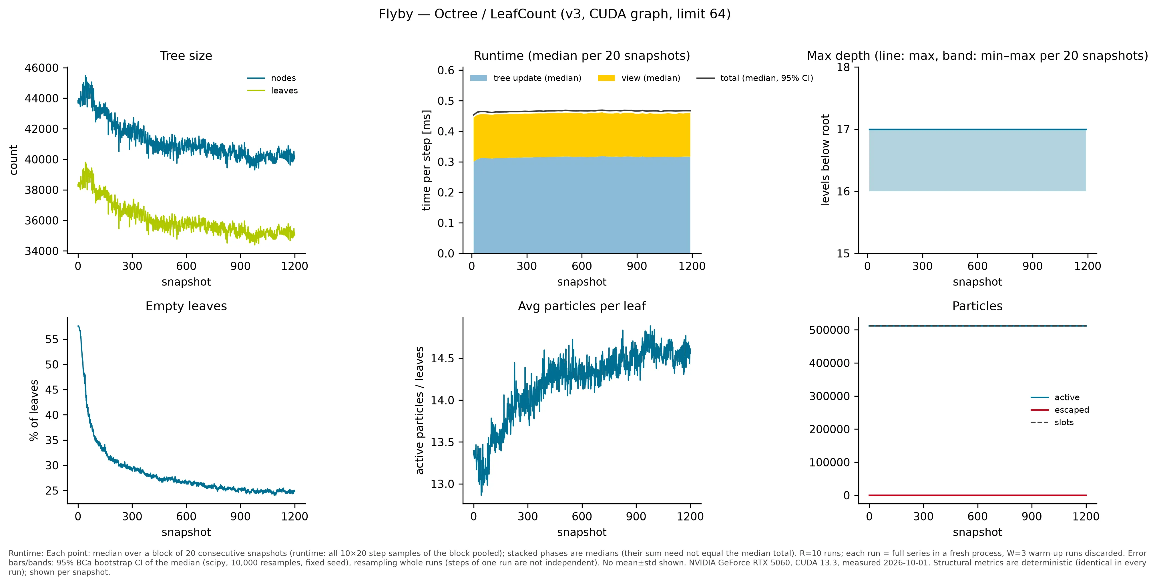
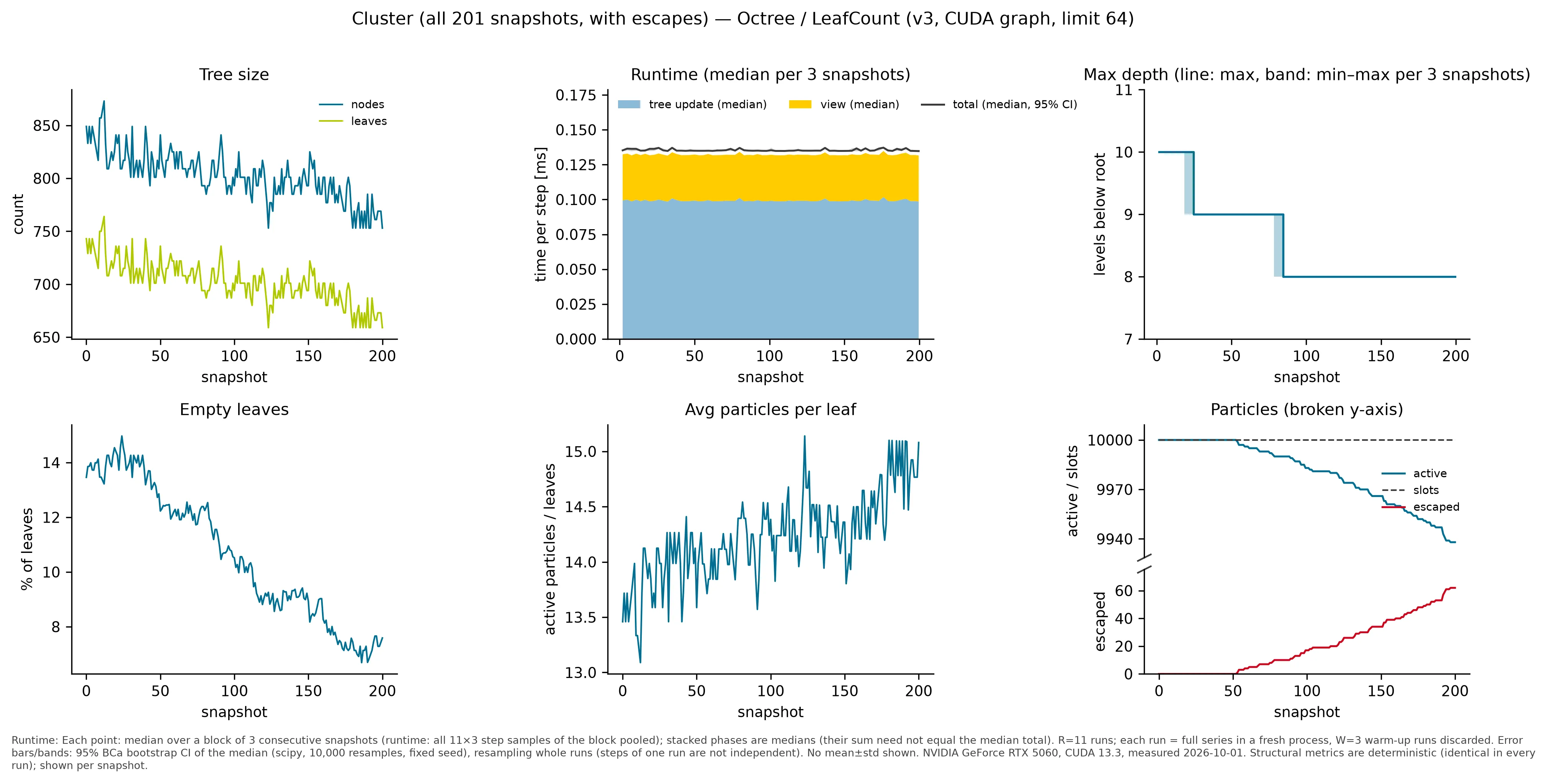
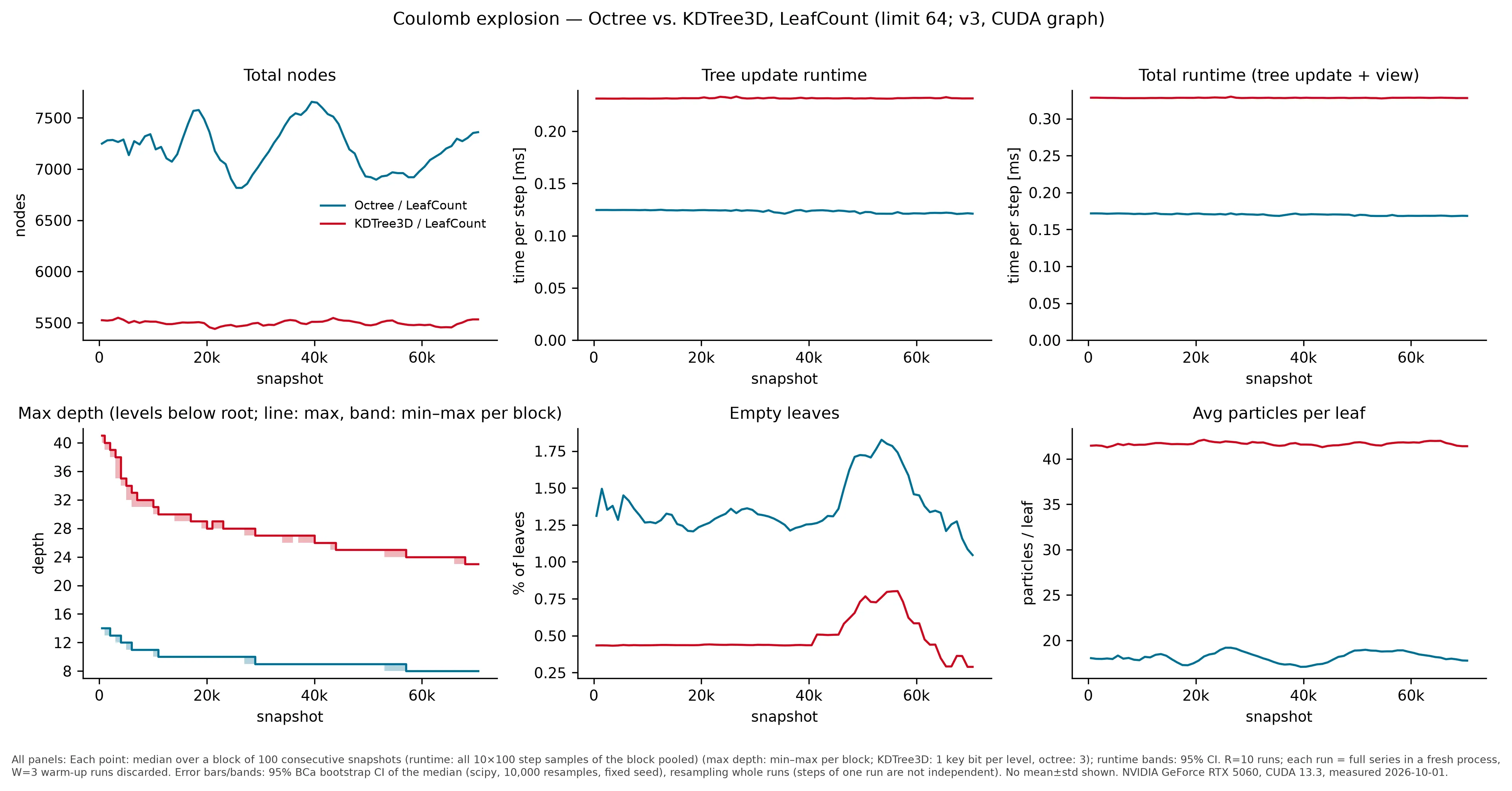
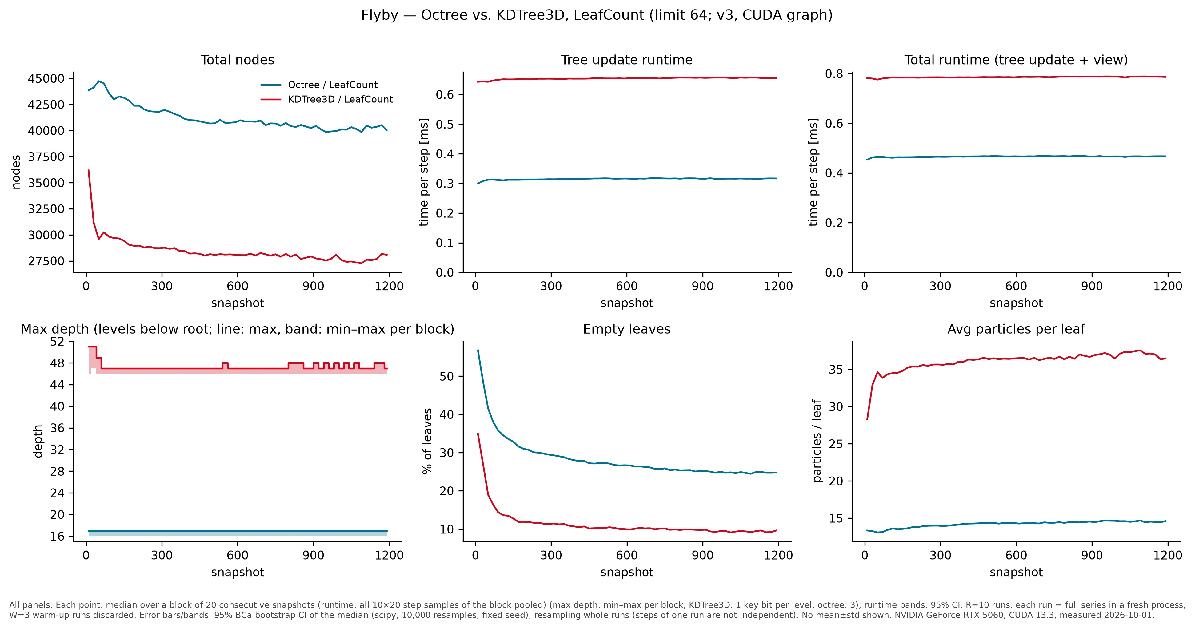
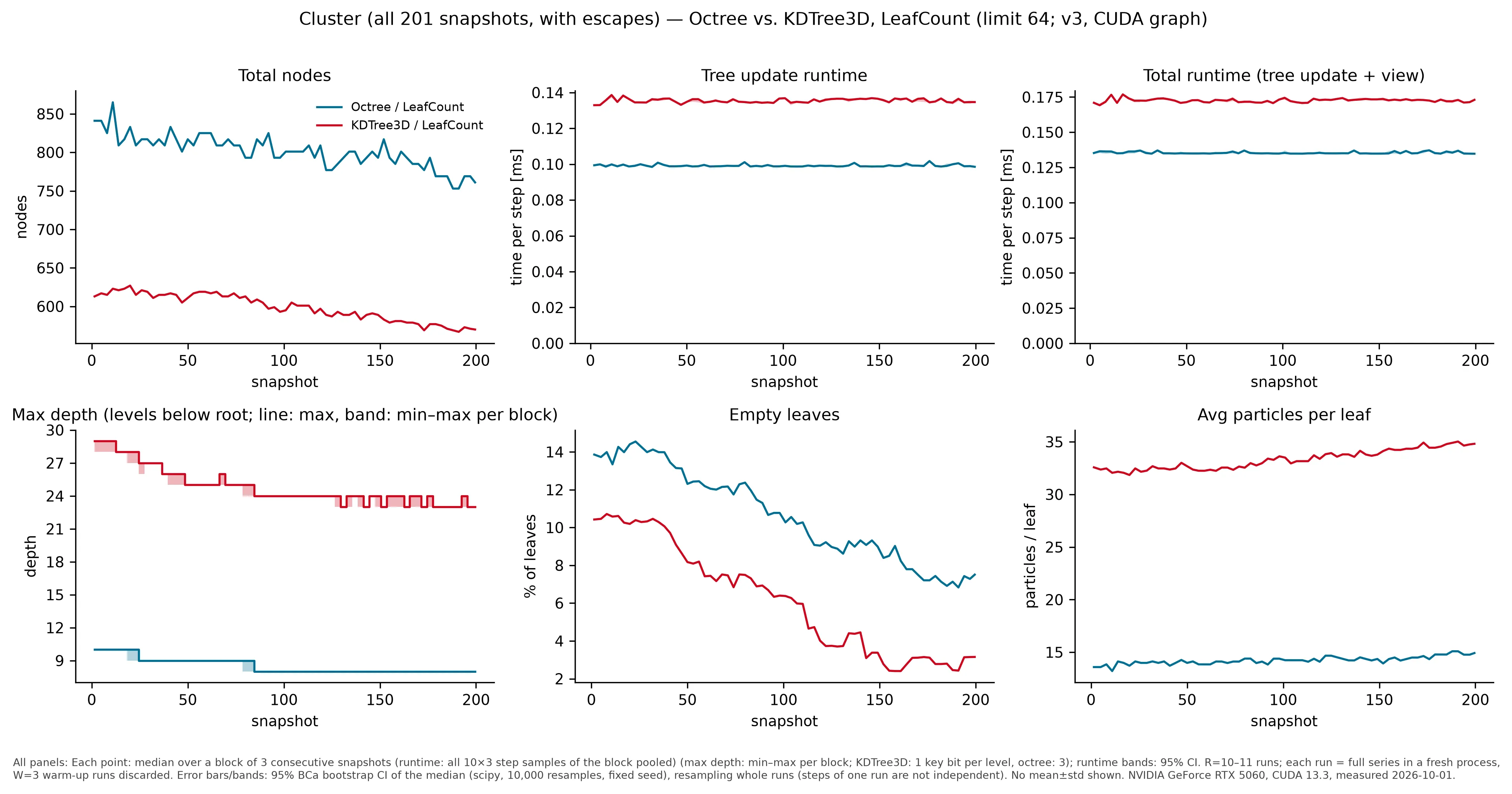
Because the update merges as well as splits, the tree size follows the particle distribution instead of only growing. In the Coulomb explosion, for instance, the maximum depth decreases as the initially dense core expands. NFCount produces more empty leaves and costs slightly more per update than LeafCount, but optimises the near-field work that the FMM performs (Figure 26). The 3D viewer in Figure 27 shows the trees themselves. In the Flyby, all particles start in a thin disk and only the centre of the domain is refined. A thousand snapshots later, the tree has followed the particles and merged cells in the centre.
figure
Coulomb explosion 114 537 particles
Flyby 512 002 particles
Cluster simulation 10 000 particles
dataset
Flyby
all particles start in a thin disk, the rest of the domain stays coarse
particles
512 002
vtk.js scene · drag to rotate, scroll to zoom
8.4 Full FMM Pipeline
The decisive question is whether the adaptive tree pays off inside the FMM. Table 4 and Figure 28 compare the full pipeline with a dense tree on the same inputs. For the early Coulomb explosion, the adaptive tree reduces the time per step from 11.27 ms to 2.36 ms (4.79×). The FMM phase alone drops from 11.11 ms to 1.98 ms, while tree update, view and interaction lists add only a fraction of a millisecond. The Flyby shows a similar gain (4.57×). For a small input such as NaCl, maintaining an adaptive tree costs more than it saves (0.55×), and for the halo subsample the dense tree already matches the distribution well (0.77×). Since these measurements stem from a separate harness, with means over repetitions and thresholds that changed over time, they support the overall speedup but not an attribution to individual changes.
| Input | Dense tree | Adaptive tree | Speedup |
|---|---|---|---|
| Coulomb explosion, early | 11.27 ms | 2.36 ms | 4.79× |
| Coulomb explosion, late | 7.10 ms | 2.04 ms | 3.48× |
| Flyby | 20.10 ms | 4.40 ms | 4.57× |
| NaCl | 0.25 ms | 0.45 ms | 0.55× |
| Halo subsample | 10.53 ms | 13.60 ms | 0.77× |
Table 4. Full-pipeline time per step (mean over repetitions), dense versus adaptive tree.
keys / sorttree updateviewinteraction listsFMM
dense tree
uniform depth
0.00 ms
first complete
first end-to-end version
0.00 ms
update API
tree rebuilt every step
0.00 ms
update API
incremental update
0.00 ms
newest
current version
0.00 ms
Mean time per step (separate FMM harness, RTX 5060 Ti, not re-measured with the construction benchmark protocol). Speed-up relative to the dense tree. Hover a segment.
8.5 Octree versus Binary Tree
Compared with the octree, the binary tree has far fewer nodes and empty leaves, more particles per leaf and a greater maximum depth (Figure 29). Its update is slightly more expensive, with 0.172 ms instead of 0.135 ms per step on the cluster dataset.
Coulomb explosion 114 537 particles
Flyby 512 002 particles
Cluster simulation 10 000 particles
9. Future Work
The main limitation concerns large dense datasets, where the 54 binary searches per leaf dominate and NFCount remains slower than Cornerstone. Reusing stencil counts between neighbouring and sibling leaves could reduce this cost considerably. A second limitation is the fixed number of passes in the graph version, which does not always reach full convergence on rapidly changing data. Adaptive pass counts and skipping capacity-sized work after convergence would address both convergence and the remaining overhead. Furthermore,
10. Conclusion
This report has shown that adaptive trees can be both GPU-friendly and suited to the FMM. Storing the tree as a sorted array of space-filling-curve boundaries turns refinement into map, scan and scatter operations and makes incremental updates natural. Refining according to near-field work instead of particle density adapts the hierarchy to the work the FMM actually performs, provided that the criterion counts particles in geometric cells rather than leaves. Reading internal nodes directly off the boundary array replaces level-by-level traversal, and the reuse of work and memory together with device-owned state and CUDA Graphs reduces an update to a fraction of a millisecond. The final implementation constructs the tree up to 2.4× faster than Cornerstone and accelerates the complete FMM pipeline by up to 4.8× compared with a dense tree.
References
- [1]H. Cheng, L. Greengard, V. Rokhlin, “A Fast Adaptive Multipole Algorithm in Three Dimensions”, Journal of Computational Physics 155(2), 468–498, 1999. doi:10.1006/jcph.1999.6355www.researchgate.net/publication/222474923_A_Fast_Adaptive_Multipole_Algorithm_in_Three_Dimensions
- [2]S. Keller, A. Cavelan, R. Cabezón, L. Mayer, F. M. Ciorba, “Cornerstone: Octree Construction Algorithms for Scalable Particle Simulations”, PASC ’23, Article 18, 2023.arxiv.org/abs/2307.06345
- [3]A. Lengvenis, fmsolvr-cuda (FMM code base), Forschungszentrum Jülich.code.fmsolvr.fz-juelich.de/a.lengvenis/fmsolvr-cuda
- [4]I. Kabadshow, “The Fast Multipole Method – Alternative Gradient Algorithm and Parallelization”, Diploma thesis, TU Chemnitz; Berichte des Forschungszentrums Jülich, Jül-4215, 2006.hdl.handle.net/2128/485
- [5]M. Dickerson, C. A. Duncan, M. T. Goodrich, “K-D Trees Are Better when Cut on the Longest Side”, ESA 2000, LNCS 1879, pp. 179–190, Springer, 2000.web.cs.ucdavis.edu/~amenta/w07/kdlongest.pdf
- [6]L. Poirrier, “An efficient space partitioning technique based on linear kd-trees for simulation of short-range interactions in particle methods”, preprint, 2009.people.montefiore.uliege.be/poirrier/download/particle/poirrier-kdtree-pp2.pdf
- [7]T. Hoefler, R. Belli, “Scientific Benchmarking of Parallel Computing Systems: Twelve Ways to Tell the Masses when Reporting Performance Results”, SC ’15, 2015. doi:10.1145/2807591.2807644spcl.inf.ethz.ch/Teaching/2025-dphpc/hoefler-scientific-benchmarking.pdf